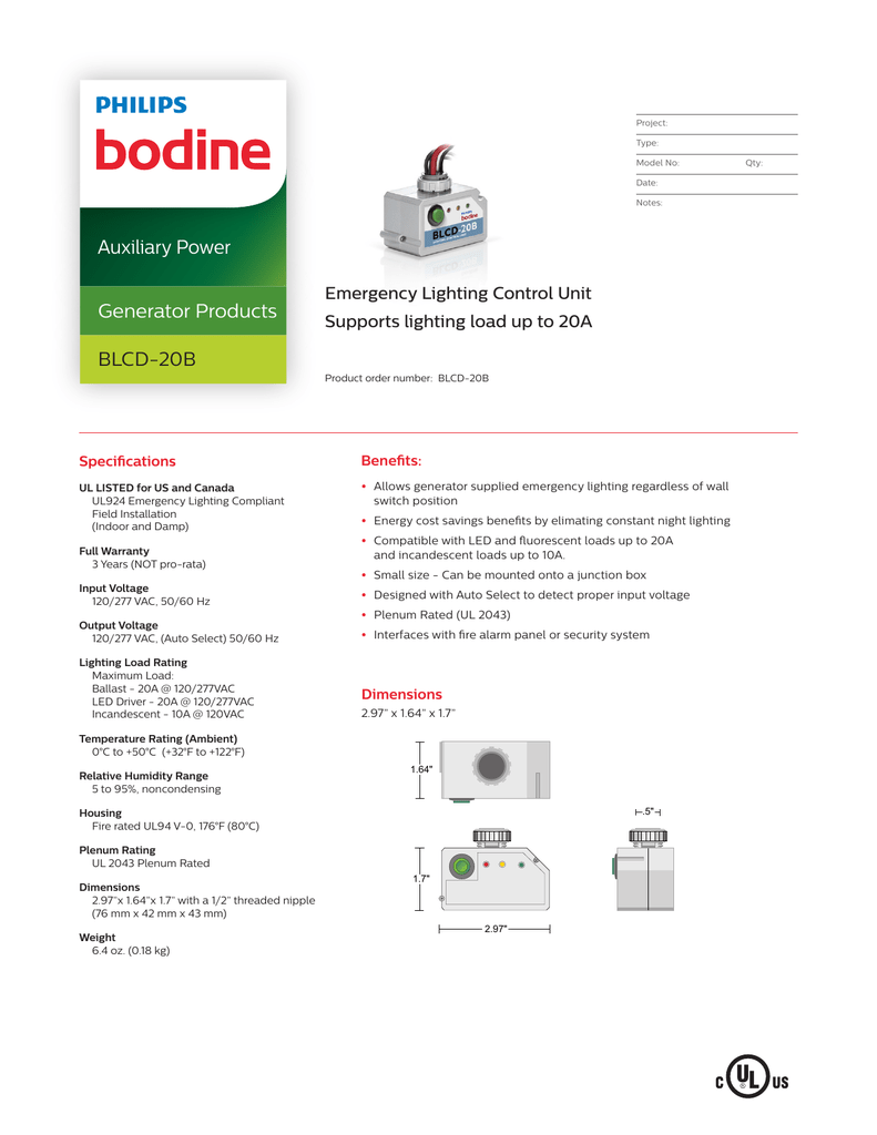
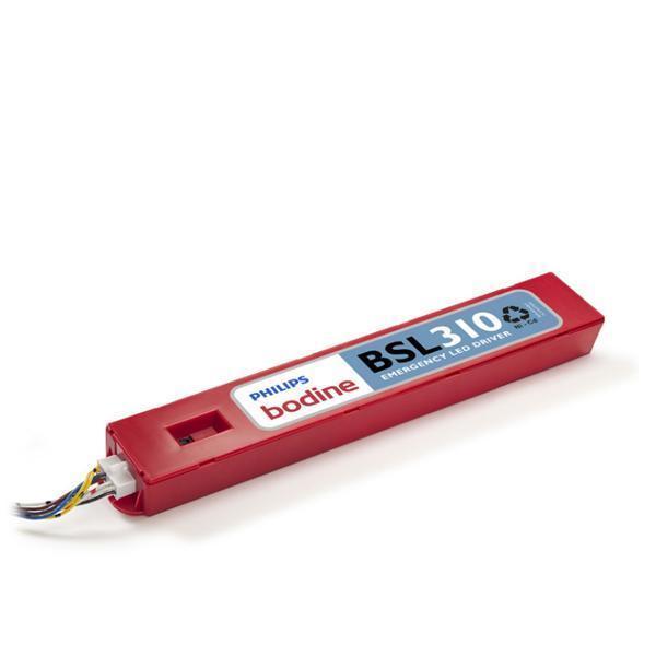
Bodine Eli S 20 Wiring Diagram
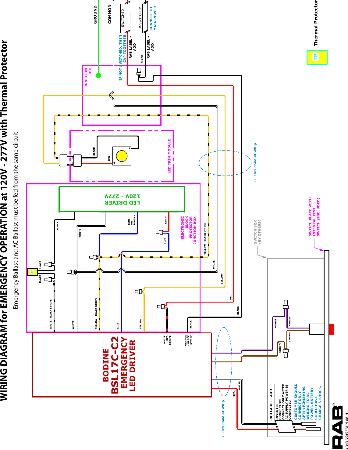
Click download pdf to view this wiring diagram. Bodine eli s 100 wiring diagram mitsubishi a700 applied power inverter electrical wiring.

35 Bodine B50 Wiring Diagram Wiring Diagram Info
Explanation of commercial naming for bodine emergency lighting inverters the typical naming convention of a bodine emergency lighting inverter is shown in the example below.

Bodine eli s 20 wiring diagram. Wiring the backup micro inverter > use the wiring diagram found on page 4 as reference. Can be installed in either direction. To verify that this is the correct wiring diagram for your bodine product, please check for the connection diagram reference number in the specifications table on the applicable item/model page.
Automatic restart upon utility return. The emergency mode output dimming voltage is selectable in 5 steps to provide nominally 20%, 40%, 60%, 80% and 100% light output. It allows the connected fixture(s) to be on, off, switched or dimmed without affecting emergency operation.
> connect the ac power source leads to the input of the backup micro inverter. 68°f to 86°f (20°c to 30°c) dimensions. There may be more than one red and black wire.
18" w x 8" d x 15" h. Maximum load power (including ac ballast/driver): It allows the connected fixture (s) to be on, off, switched or dimmed without affecting emergency operation.
The unit consists of a sealed lead calcium battery, charger and electronic circuitry in one. > connect the output leads of backup micro inverter to the ac ballast/driver. Conduit wiring for remote installation;
400 watts uses 4 batteries do not exceed total nameplate rating of equipment. It allows the connected fixture (s) to be on, off, switched or dimmed without affecting emergency operation. Delivers up to 25 watts of output
Philips bodine emergency wiring diagram www mit edu, philips eli s 20 installation instructions manualslib, united states charlotte, surplus process equipment lab, www mit edu, korics co kr, philips bodine 13 to 215w fluorescent emergency ballast, philips eli s 20 installation instructions Local bodine sales representative for more information. It allows the connected fixture(s) to be on, off, switched or dimmed without affecting emergency.
Less than 168 hours (meets ul924) battery protection. Bodine type wpm, filtered pwm speed controls for permanent magnet dc (pmdc) gearmotors and motors. Wiring diagram red black 12 volt battery 12 volt battery orange black red white brown gray orange black white line in line out local switch note:
Connect one set of wires per battery. > wire the ac ballast/driver with the lamp in accordance with manufactures installation instructions. Standards ul listed, csa certified.
Corepro glass high lumen bulbs. The "s" signifies that the output voltage is This pdf file is an updated version of our printed user manual p/n 07400209, that is packaged with stock models 0780, 0781, 0783 and 0784.
Refer to illustration 3 below to wire The eli series operates a maximum load of20 or 25 w at unity power factor. Eco led type b lamp is polarity neutral.
It shows the components of the circuit as simplified shapes, and the knack and signal associates amongst the devices.

30 Bodine Motor Wiring Diagram Wiring Diagram Database

Bodine B100 Wiring Diagram Wiring Diagram Schema

26 Wh5 120 L Wiring Diagram Wiring Database 2020

35 Bodine B50 Wiring Diagram Wiring Diagram Info

Wiring Diagram For Philips Bodine Elis100

Bodine Led Wiring Diagram Wiring Diagram Schema

Bodine Led Wiring Diagram Wiring Diagram Schema

Bodine B30 Wiring Diagram Wiring Diagram Schema

Emergency Lighting Inverter Wiring Bodine Eli S 250 250 Watt Line Voltage Inverter Emergency

Bodine Led Wiring Diagram Wiring Diagram Schema

35 Bodine B50 Wiring Diagram Wiring Diagram Info
26 Wh5 120 L Wiring Diagram Wiring Database 2020

26 Wh5 120 L Wiring Diagram Wiring Database 2020

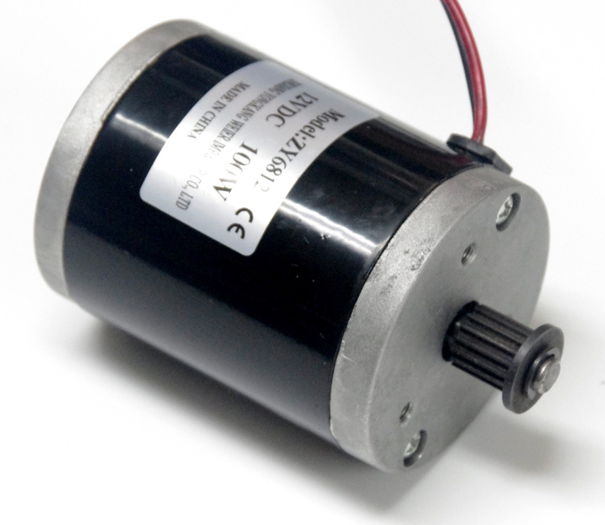
30 Bodine Motor Wiring Diagram Wiring Diagram Database
Bodine Electric Dc Motor Wiring Diagram CIKMUTIARAPUNYACERITA

